Celler Straße 67 - 69
38114 Braunschweig
Germany
Fon: +49 (0) 531-129 399 0
Fax: +49 (0) 531-129 399 29
Mail: info@tbksoft.com
Web: http://www.gwj.de
Straight and helical bevel gears
Features
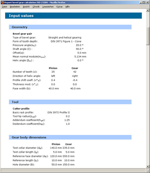
- Geometry of straight and helical bevel gears according to ISO 23509 and DIN 3971
- DIN bevel gears: tip cone, root cone and reference cone intersect in a common point (Gleason)
- Standard depth: root cone and reference cone intersect in a common point (Gleason/Konvoid)
- Klingelnberg bevel gears: tip cone, root cone and reference cone are parallel (constant tooth depth)
- Recommended range of values for facewidth
- Bevel gear pairs with shaft angle = 90°, without offset
- Basic rack profiles according to ISO 53, DIN 867 and DIN 3972 can be selected or defined individually
- Consideration of profile shift and thickness modification
- Check for undercut and pointed teeth, suggestions for tooth tip chamfering
- Calculation of transverse contact ratio, overlap contact ratio and total contact ratio based on virtual spur gear toothing
- Turning dimensions with lengths of cone and angles, calculation and direct input of mounting distance
- Suggestions for backlash according to Klingelnberg or Niemann, backlash can be defined individually
- Determination of the tooth depth, tooth thickness and chordal tooth thickness
- Allowances according to DIN 3965 for deviations of several parameters, shaft angle deviation and common apex deviation, gear quality, appropriate allowances and permissible deviations according to ISO 17485 respectively
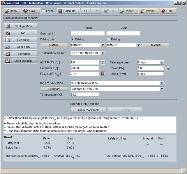
- Load capacity calculation according to ISO 10300 Method B1 with integrated material and lubricant database
- Mode of operation: swelling, alternating and oscillating
- Calculation of safeties for fatigue or limited life strength and static strength (tooth root, flank / pitting, scuffing)
- Detailed calculation report in HTML and PDF format
Description
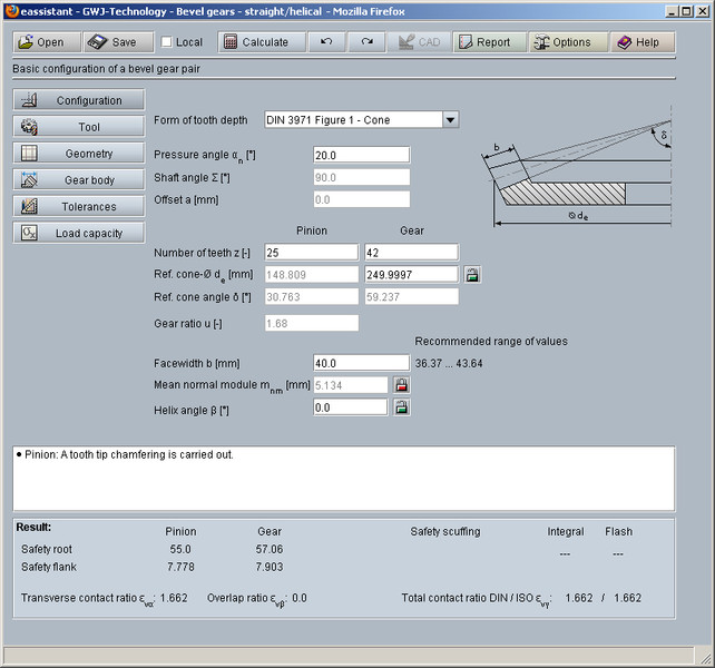
This gear calculation module allows a fast and easy calculation of straight and helical bevel gears according to ISO 23509 und DIN 3971. The user can select different forms of the tooth depth. The tooth depth according to DIN 3971 - Figure 1 is the configuration where reference cone apex, tip cone apex and root cone apex intersect in a common point. This tooth depth is typical for straight Gleason bevel gears. The standard depth taper changes in proportion to the cone distance. If the root line is extended, it intersects the axis of the pitch cone apex. This tooth depth is used for straight Gleason bevel gears and Konvoid bevel gears (Modul machines). For Klingelnberg bevel gears, the face angle, root angle and reference cone angle are parallel (constant tooth depth).
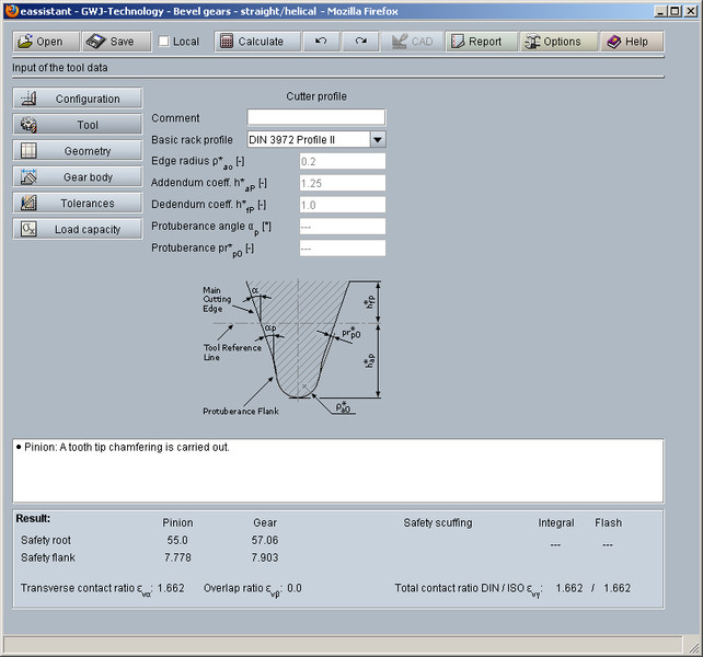
A recommended range of values for the facewidth is shown next to the input fields. Standard basic rack profiles according to ISO 53, DIN 867 and DIN 3972 are available for the calculation or can be defined individually.
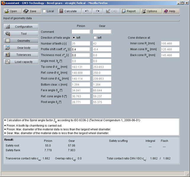
Profile shift modification as well as thickness modification are also included in the calculation. Undercut is controlled, the calculation module suggests a minimum profile shift modification in order to avoid undercut. If the tip tooth thickness at the inner cone is too small, a tooth tip chamfering is carried out automatically. The user is able to manually define the individual tooth tip chamfering.
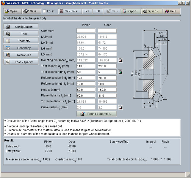
Based on a virtual spur gear toothing, transverse contact ratio, overlap contact ratio and total contact ratio are calculated in accordance with ISO 23509. Turning dimensions with lengths of cone and angles are determined. Other gear body parameters, including tip circle distance and mounting distance, are determined as well. The user can modify the mounting distance. The module provides proposals for the amount of backlash according to Klingelnberg or Niemann. A backlash can be defined individually.
Futhermore, allowances (according to DIN 3965) for shaft angle deviation and common apex deviation are available. The gear tooth quality can be selected in accordance with ISO 17485. The tolerances, determined from the gear tooth quality, are calculated as well. Tooth depth, tooth thickness and chordal tooth thickness are determined automatically.
In addition to the geometry calculation, a calculation of the load capacity according to ISO 10300 Method B1 is possible. The user can calculate the safeties for fatigue or limited life strength and static strength (tooth root, flank / pitting, scuffing). Material and lubricant databases support the user. Additionally, the mode of operation is considered (swelling, alternating and oscillating).
The redo/undo function and the calculation report in HTML and PDF are also available in this module.