Celler Straße 67 - 69
38114 Braunschweig
Germany
Fon: +49 (0) 531-129 399 0
Fax: +49 (0) 531-129 399 29
Mail: info@tbksoft.com
Web: http://www.gwj.de
Shaft calculation with strength according to DIN 743
Features
- Calculation of full and hollow shafts
- A free number of cylindrical and conical shaft segments
- Calculation with two or more bearings is supported
- A free number of bearings is possible
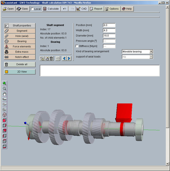
- Interactive modelling of the shaft in 2D and with 3D view
- Possible loads: forces and moments, gears, additional masses, etc.
- Calculation of bearing forces; interactive diagrams of forces, moments, deflection, bending angle, equivalent stress and oscillation shape of critical speeds and static torsion
- Calculation of critical speeds (bending and torsion) with consideration of the moment of inertia, deflection due to shear and gyroscopic effects
- Strength calculation according to DIN 743 includes the calculation of notch factors
- Standard notch cases according to DIN 743 as well as own input of notch factors
- Different material treatments for notches
- Direct input of loads for notch cross sections independently of other loads affecting the shaft
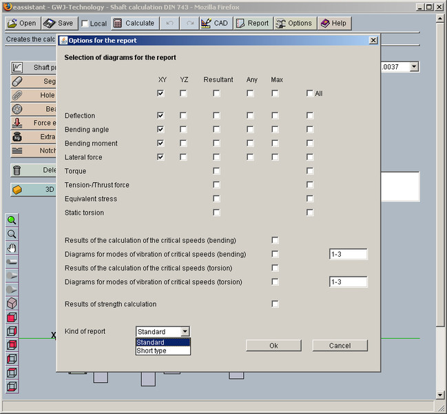
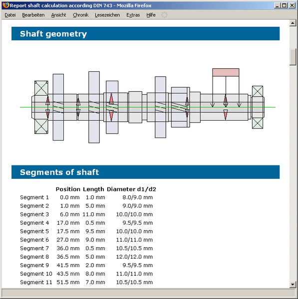
- Configurable report with detailed results and diagrams in HTML and PDF format
Description
The shaft calculation has a geometry and a calculation part.
In the geometry part
- material,
- speed,
- direction in space and of rotation,
- shaft geometry,
- bearings,
- loads and
- notch effects
are defined for the calculation.
For the shaft geometry, a free number of cylindrical and conical full and hollow shaft segments are usable. The shaft calculation needs a minimum bearing number of two. From a number of two bearings a free number can be defined. So an overdefined calculation with more than two bearings is also supported by the shaft module. Stiffness and pressure angle of the bearings are also provided for the input.
Additional to the direct input of forces and moments, intelligent load elements are also usable. There are gears, additional masses or coupling/motor. For the strength calculation according to DIN 743 all notch effects of the standard are definable. Beyond the special notch effect "smooth shaft" was brought into the calculation. The reason for that is to give the possibility for a strength proof at a high loaded smooth shaft segment. In addition to the interactive 2D geometry, input a 3D view is also existing.
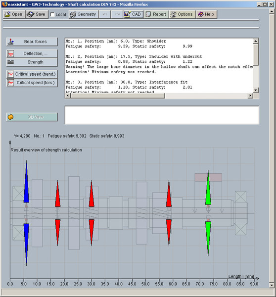
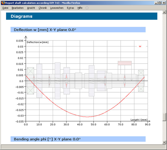
In case the definition of the shaft geometry, bearings and loads is finished, the calculations can be started. In addition to the calculation of the bearing forces and the static torsion, the several diagrams of forces, moments, deflection, bending angle and the equivalent stress will be displayed. The diagrams of the results are interactive. For example: with a mouse click the value for the bending of the selected shaft position is given out in the message window.
The strength calculation provides a complete static and fatigue proof of strength according to DIN 743. The calculated safeties for the several cross-sections will be displayed in a result graphic in three different colours. Cross-sections with red colour haven't reached the minimum safety. Green colour is for cross-sections with safeties from the defined minimum safety to the triple. Cross-sections with the blue colour have a safety more than the triple of the minimum safety. The exactly values of the safeties are given in the result text field or shown per mouse click in the graphic result window.
The calculation of critical speeds (bending and torsion) is also possible. Here you have the possibility to take the moment of inertia into consideration as an option. For the bending modi, the options for deflection due to shear and gyroscopic effects are also available.
Is the calculation finished, the user can generate a report with a desired size. Several diagrams and results of the strength calculation can be selected in the report configurator. The report is available in HTML and PDF format.