Celler Straße 67 - 69
38114 Braunschweig
Germany
Fon: +49 (0) 531-129 399 0
Fax: +49 (0) 531-129 399 29
Mail: info@tbksoft.com
Web: http://www.gwj.de
Cylindrical gear pairs according to DIN 3990 / ISO 6336 and further standards
Features
- Geometry of cylindrical gear pairs - external and internal gears, spur and helical gears - according to DIN 3960, DIN 3961, DIN 3964, DIN 3967, DIN 3977 and DIN 868
- Rough dimensioning: proposals for possible design variations based on entered power data, material, desired transmission ratio and optional for a centre distance range, set out in table form
- Input of pressure and helix angle in decimal degree or in degree, minute and second
- Alternative input for normal module as diametral and circular pitch
- Consideration of profile shift modification with optimization function for balanced specific sliding and for other criteria, for example the max. tooth root safety
- Extended range of possible profile shift modification (addendum modification)
- Specification of working centre distance or calculation of this from given profile shift coefficients
- Specification of a fixed working centre distance independently from the profile shift sum
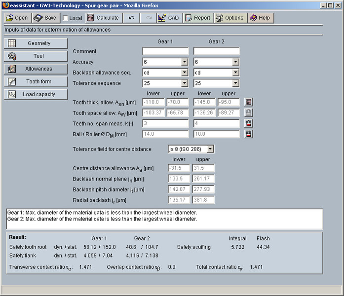
- Allowances for tooth thickness and centre distance can be selected from a database or can be defined individually
- Addendum chamfer / tip corner radius can be considered in the calculation
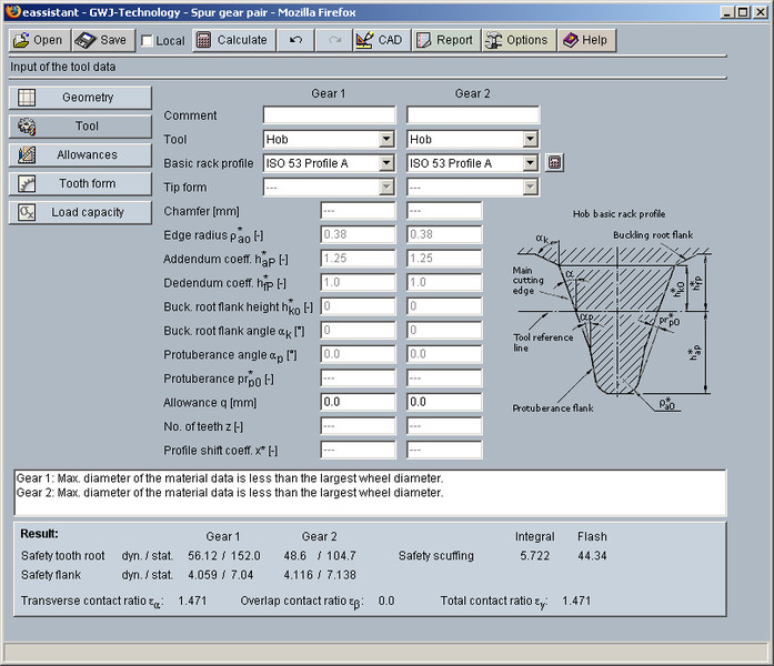
- Standardised basic rack profiles for tools according to ISO 53, DIN 867 and DIN 3972 are selectable or individually definable, protuberance tools with and without allowance, dimensioning function for special basic rack profiles, protuberance tools with shifted profile reference line, topping tools as well as tools with semi topping flank
- Full-depth teeth and stub tooth gears possible
- Type of tools: hob, gear shaper cutter and constructed involute
- Individual definition of the factor for the minimum tip tooth thickness
Definition of the factor for the minimum gear ring thickness - Calculation of the test dimensions
- Calculation of the tooth thickness allowances based on measured values or given test dimensions
- Gear qualities / tolerances according to DIN 3961, DIN 58405, ISO 1328 and ANSI / AGMA 2015
- Check for meshing interferences on the basis of the accurate gear tooth form with consideration of all tolerances
- Display of the accurate gear tooth form with animation/simulation of the tooth mesh also for different tolerance fields
- Definition and consideration of profile modifications: linear and circular tip relief, linear and circular root relief, symmetric profile crowning
- Dimensioning of long or short profile relief, specification of the relief length or start diameter of the modification
- Dimensioning of the amount of profile relief with specification of the torque in percent of the nominal torque as well as display of the no-load transverse contact ratio
- Definition and consideration of flank modifications: end relief, symmetric and asymmetric lead crowning including recommendations for amounts of the end relief or crowning according to reference values in DIN 3990
- Calculation with non-integer number of teeth, i.e., number of teeth with decimal places (available on request)
- Calculation with helix angle greater than 45 degree (available on request)
- Geometry calculation of internal cylindrical gears with equal number of teeth is also possible (geometry of involute splines)
- Dimensioning of internal gear pairs with small difference between the number of teeth (|z2| - z1 < 4) possible
- Calculation of load capacity according to DIN 3990 Method B, ISO 6336 Method B and ISO/TR 13989 (scuffing) as well as ANSI / AGMA 2101-D04 (identical to ANSI / AGMA 2001-D04) with integrated material and lubricant database including ultra-clean steels with modified Wöhler curves deviating from DIN / ISO
- Calculation of load capacity with load spectrum according to ISO 6336 Part 6, determination is based on the Palmgren-Miner rule: load-dependent K-factors are calculated for each torque class; safeties are determined by way of iteration until the sum of damage parts is obtained
- Definition of load spectra including face load coefficient KHß and temperature, specification of the load application factor also possible in combination with the load spectrum
- Calculation of the load capacity for plastic materials according to VDI 2736
- Plastic materials available
- Maximum possible tooth normal force and maximum transmissible torque based on the required static and dynamic tooth root safeties
- Diagram of flash temperature (contact temperature)
- Consideration of grinding notches in the load capacity calculation
- Optimal hardening depth, manual input of hardening depth and consideration in the load capacity calculation
- Selection of mode of operation is possible for swelling, alternating and oscillating
- Consideration of rolling, shot peening, grinding or machining for the tooth root
- Calculation of the number of load changes or individual definition or specification of the number of tooth meshes
- Optional entry of the carried width for the tooth root with different gear widths of gear 1 and 2 (DIN 3990 / ISO 6336)
- Work hardening factor can be defined
- Life factors can be adapated (ISO 6336)
- Power loss by tooth friction, gearing efficiency according to Niemann
- Calculation of the safeties for fatigue or limited life strength and static strength (tooth root, flank / pitting, scuffing)
- Min. / max. transverse contact ratio
- Unit switch between metric and U.S. customary unit system, unit switching function also for single parameters
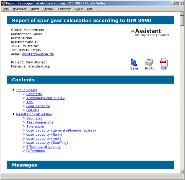
- Configurable report with detailed results in HTML and PDF format
- Output of CAD data via TBK CAD-PlugIns or DXF interface
- Output in normal section of the tooth gap in 2D DXF format
- GDE output (Gear Data Exchange) as XML file according to the VDI / VDE guideline 2610
Description
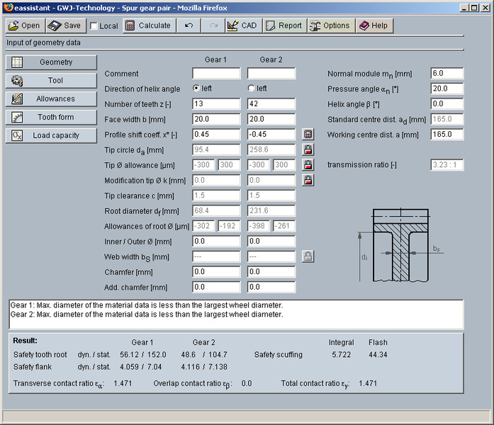
This gear calculation module allows the simple and fast calculation of the geometry of cylindrical gear pairs according to DIN 3960, DIN 3961, DIN 3964, DIN 3967, DIN 3977 and DIN 868. Profile shift modification, addendum chamfer and allowances will be taken into consideration. Allowances of tooth thickness and centre distance can be comfortably selected from the database. For the profile shift modification factor, an optimization function for balanced specific sliding is available. For the calculation, the working centre distance can be specified or can be calculated from given profile shift coefficients. Different standardised basic rack profiles for tools according to ISO 53, DIN 867 and DIN 3972 can be selected or defined individually for the calculation. Full-depth teeth and stub tooth gears are possible. Furthermore, the test dimensions will be calculated. For these, the required number of the teeth for span measurement and the diameter of ball or pin will be determined automatically by the program or can be entered by the user. In addition, a backward calculation of the tooth thickness allowances from given test dimensions is also possible.
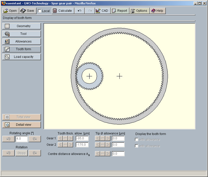
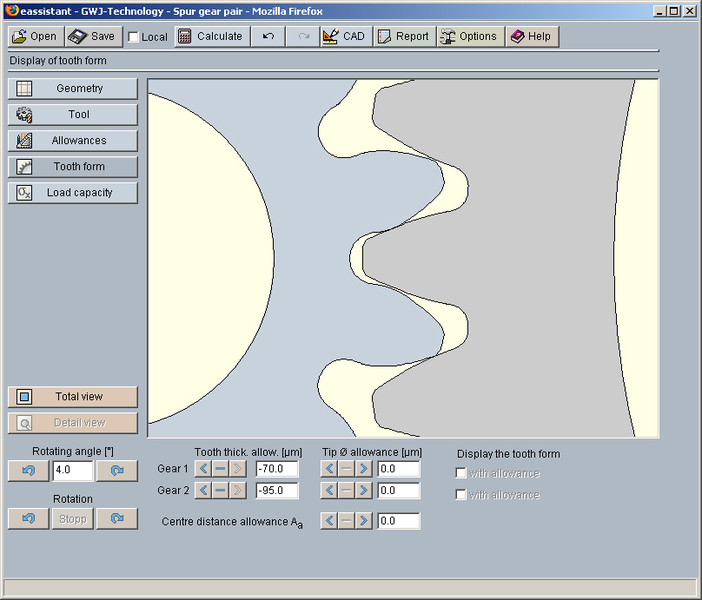
A special highlight of the calculation module is the display of the accurate gear tooth form with animation/simulation of the tooth mesh. For this representation, the lower, middle and upper allowances for the tooth thickness, the tip circle diameters and centre distance can be selected. Additional, the program gives hints and warnings (e.g., for possible meshing interferences). A check for meshing interferences occurs in the background based on the accurate gear tooth form.
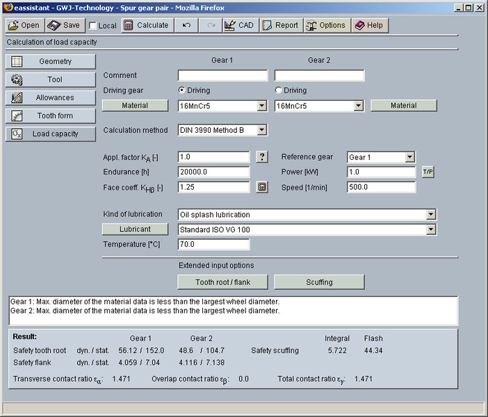
In addition to the geometry calculation, the load capacity according to DIN 3990 Method B is also available. Herewith the safeties for fatigue or limited life strength and static strength can be calculated. The calculation of surface durability (pitting), tooth bending strength and scuffing according the flash and integral temperature method is carried out. A diagram for the contact temperature over the length of the line of action is also available.
Alternatively, the load capacity calculation of the surface durability (pitting) and tooth bending strength according to ISO 6336 (2008) Method B is selectable. For the scuffing load capacity the ISO/TR 13989 is integrated.
There is a calculation of load spectra for cylindrical gears according to ISO 6336 Part 6. The determination is based on the Palmgren-Miner rule and the load-dependent K-factors are calculated for each torque class. The safeties are determined by way of iteration until the sum of damage parts is obtained. This method, demanded by the wind energy industry, is very accurate.
The materials and the lubricant can be comfortably selected from the database. Furthermore, other effects (grinding notches, mode of operation, etc.) can be taken into consideration.
The redo/undo function and the calculation report in HTML and PDF are also available in this module.