



What happens to the contact pattern of a bevel gear when the entire gearbox deforms under load?
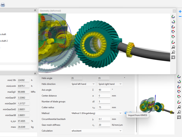
With the latest version of SystemManager, the extension for GWJ Technology’s calculation solution TBK, a new interface to Klingelnberg’s KIMoS bevel gear software is now available.
This new coupling enables the effects of system deformation and stiffness on the relative positioning of bevel gear components to be taken into account in the subsequent tooth contact analysis.
KIMoS ⇒ SystemManager ⇒ KIMoS
1. Define the bevel gear geometry:
The bevel gear set is designed in KIMoS and exported via an XML interface file.
2. Import into SystemManager:
The KIMoS data is imported into the corresponding bevel gear connection in SystemManager.
3. Calculate the complete gear system:
For different load cases, SystemManager determines the relative positions of pinion and gear while considering the deformations and stiffnesses of the complete system.
4. Transfer the results back to KIMoS:
After the system calculation, the KIMoS XML file can be exported again with the additional load-dependent data for all load cases and imported into KIMoS via the Load Spectrum Editor.
5. Perform LTCA and optimize the design:
The resulting data can then be used for a Load Tooth Contact Analysis (LTCA) across the complete load spectrum, allowing the loaded contact pattern of the bevel gear pair to be analyzed and optimized.
The bevel gear pair is no longer considered in isolation. Instead, the interaction between the gear geometry and the behavior of the complete transmission system under load can be taken into account.
From idealized gear geometry to realistic, load-dependent bevel gear design.